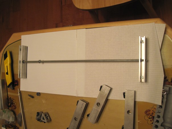
After taking some time away from the project to think about how I was going to fabricate the X, Y and Z axis mechanical aspect, I finally rolled up my sleeves and tried out my first idea. Using the aluminum stock and a drill press I fashioned some very solid mounts for the roller bearings and the thread stock.
Having the goal of just getting my first axis working and thus allow me to review how the assembly works, before committing to having all of them done this way ( in case there is an issue).

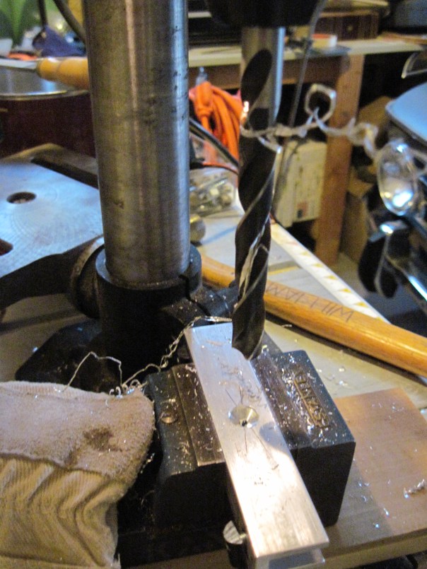
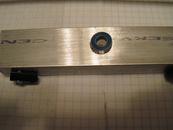
Drilling out the center of the beam… this will house the roller bearing.
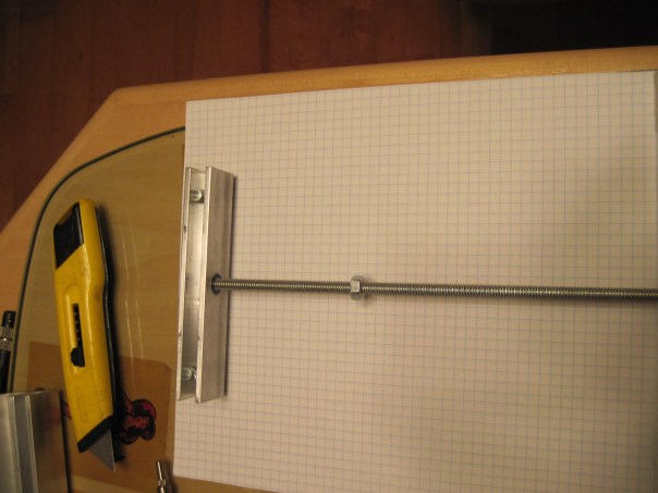
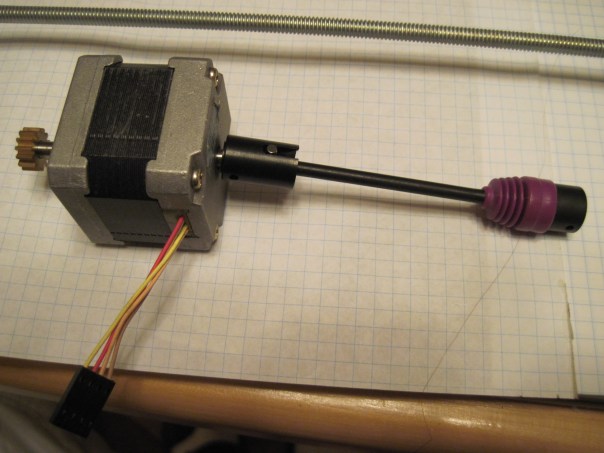
Posting the other end where the stepper motor will mount.
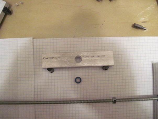


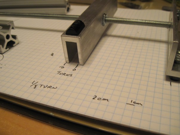
Keeping it simple is my goal… so hammering in a single nut into the plate bracket made sense… and if needed I can adjust it.
Of course I am back to building now so i will be sure to post the next stage of the X axis. and how things are progressing. It seems like this will be a fall project as right now the weather is great for riding my old scooter.
I think once this axis is fully assembled I can experiment with the motors, the controllers, the emergency stop and limit switches… the wiring harness will be interchangeable thus I can try each section of the harness only using the X axis. Check each electronics board will be the next post… hope to have you reading it very soon!
